Discover dooba
Introduction
Hello and welcome to the "Discover Dooba" tutorial!
This is meant to serve as an entry point for anyone just discovering Dooba. This tutorial is pretty long because it covers many topics, some of which you may already be familiar with.
Here we will start by exploring different aspects of the Dooba universe and embedded development in general. We'll cover the main tools provided by the SDK to help you build cool stuff. We will also go through building a first "Hello world!" example project. After reading this tutorial, you should have a clearer understanding of what it takes to build cool electronics using the Dooba ecosystem.
So let's jump right in, starting with some of the most fundamental concepts - what are computers?
Different architectures
In general, "computers" can be simplified as machines executing sequences of instructions to accomplish specific tasks.
The minimum requirements for this usually include a "processor" (the part that executes the instructions) and some memory (where the instructions are stored and executed from).
While executing instructions, the processor will operate on "data", which also needs to be stored somewhere.
This is where the major split in computer architecture appears: are "code" (instructions) and "data" stored in the same memory, or in separate, dedicated memories?
Here we will quickly go over the two architecture families: Von Neumann and Harvard.
(If you want to dig deeper on this topic, go have a look at Computer Architecture on Wikipedia.)
Harvard
Earliest computers like the famous Harvard Mark I featured a Harvard architecture. These needed a memory to store the sequence of instructions they would execute, and also another memory to hold some computation data.
Typically, the "program" memory would be read-only or even mechanical, while the data would be mostly read/write (though sometimes also mechanical-based).
While it may seem that this is now an obsolete way to design computers, it does provide advantages, and many products built today still use it. Such devices are simpler to manufacture and program. They also offer some efficiency benefits due to having separate data pathways (memories can operate at different speeds and be accessed simultaneously).

Harvard Architecture
Von Neumann
Pretty much everything we call a "computer" today features a Von Neumann architecture. Whether it's an enterprise server, a small laptop or even a smartphone, they all have a shared memory containing both code and data.
In a Von Neumann machine, the processor has a single address space from which it can read and write both instructions and the data manipulated by these instructions.
From the processor's point of view, there is no distinction between code and data. This has a significant consequence: code can load more code, and even modify itself.
This is one of the first and most important requirements for modern operating systems: the ability to load some data from a permanent storage (hard drive for example) as code and then have it executed as a separate process.

Von Neumann Architecture
Embedded programming
Embedded programming is a loosely-defined term referring to development for hardware that is generally not considered "computers". Think washing machines, automobiles, televisions.
The difference with "traditional" programming resides mostly in the constraints imposed by the hardware. As seen previously, most modern computers are based on a Von Neumann architecture. Most of these therefore have an operating system running. Applications written for such environments can focus on their "business" logic and rely on the operating system to provide them with all the utilities they need (managing the hardware, files, network access, etc...) in a generic manner.
Embedded programming includes many types of devices (both Harvard and Von Neumann) but generally implies running "alone" directly on the hardware, with no operating system to provide any help.
Microcontrollers
Microcontrollers are electronic devices that include a processor, some memory, and usually some I/O peripherals into a single silicon die. They are basically computers on a chip.
For simplicity, they are often designed with a Harvard architecture (though many are not), featuring some flash memory to store the program and some SRAM to hold the data.

ATmega1284P microcontroller (in TQFP44 Package)
These devices typically include some I/O (in the form of standard busses or input/ouput pins), which the application can control.
Putting all of this together means that microcontrollers can be used in electronic circuits to control digital signals with code.
Here at Dooba, we love microcontrollers. We believe they offer great possibilities and allow developers to dive deeper into the hardware they use. This is why we provide tools to help you work with microcontrollers. Our favorite family of micros is the famous AVR family, developed today by Microchip.
The heart of our ecosystem is the ioNode - a small device that hosts an atmega1284p and enough circuitry to program it and have it communicate easily through USB. The ioNode features a USB-UART (sometimes referred to as a 'serial to USB adapter'), which is what allows communication with the microcontroller very easily from any computer.

An early (pre-release) version of the ioNode
Hardware
Before we go any further, it's important that we clarify some vocabulary. In particular, some of the concepts presented here will be used over and over again throughout the entire documentation and tutorials - it is paramount that you familiarize yourself with them.
Glossary
GPIO - General Purpose I/O (Pins and ports)
As seen earlier, a program running inside a microcontroller can control some I/O's. These are input & output pins - electrical connection points - that can be set to a logic value of 1 or 0 (output), or configured as inputs so the program can "read" what logic value is being applied.
This is where the name 'GPIO' comes from - these pins can be used for any purpose. They can "talk to" any other electronic system as long as the voltage is compatible.
Generally, most electronic logic circuits use 0V for a logic '0' (low) and either 5.0V or 3.3V for a logic '1' (high). The ioNode runs at 3.3V and therefore its I/O pins use 3.3V for a logic '1'.
A common way to see this in action is to attach a LED (with a resistor so it doesn't fry!) to one of these pins:

Our program is now able to turn that LED on or off. We will see how to do just that later on.
We can also use the GPIO as input. Let's connect a small switch (push button) to one of these pins:
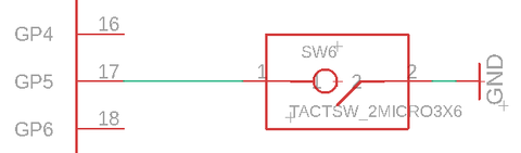
Our program is now able to detect a press of that button.
As we will see later, some of the I/O pins have alternate functions - this means they can be used for things other than simply reading/writing digital values.
I2C, SPI, UART (Standard interfaces)
Using GPIO is fine for controlling LED's, reading buttons or other simple forms of communication. However when dealing with more complex components, chips or modules, we will need to exchange more complex data. Standard protocols exist to facilitate communication between electronic systems. These are often implemented in hardware directly inside microcontroller chips.
The ATmega1284P includes dedicated hardware transceivers for all of the protocols presented here (SPI, I2C & UART). This allows programs to communicate easily, without having to individually toggle the signals for every bit.
I2C
I2C uses only two digital lines and allows a master to communicate with a large number (typically up to 127) of slave devices.
One line is used as clock signal (SCL) while the other is used as a bi-directional data signal (SDA). Everytime the clock signal is pulsed, the data signal should be set or read. Eight successive pulses form a byte of data.

The I2C Bus
I2C works by prefixing each chunk of data with an address indicating for which slave device the communication is for.
If you want to look at how this protocol works in greater detail, the Wikipedia page has a lot of information.
We provide a library to make I2C communication easy. See the details here: I2C.
Note: because of the way I2C works, it requires adding "pull-up resistors" on both signal lines (SCL & SDA).
SPI (Serial Peripheral Interface)
SPI uses 3+N digital lines and, just like I2C, allows a master to communicate with a number of slave devices.
One line is used as a clock signal (SCK), while two others are used as unidirectional data lines: MOSI (Master-Out-Slave-In) and MISO (Master-In-Slave-Out). One additional line is required for each slave device: the chip-select signal (sometimes called slave-select). While I2C uses addresses to select slave devices, SPI uses a dedicated signal line per slave. This removes the overhead incurred by sending the address byte, which allows for faster transfers.

The SPI Bus
A library for SPI communication is also provided. See the details here: SPI.
UART (Universal Asynchronous Receiver/Transmitter)
UART uses only two lines and allows bi-directional asynchronous full-duplex communication between two devices.
Each device uses one line to transmit (TX) data, while receiving data on the other (RX).

The UART
Because no clock signal is used to synchronise communication, it is critical that both devices "agree" on the bitrate at which to communicate when using UART. Typically UART is implemented in hardware and provides accurate bitrate control.
What's a Module
The Dooba ecosystem is built around hardware 'modules'. Those generally provide one or more features in a somewhat self-contained form-factor.
For example, the Aecho module provides MP3 decoding and audio output capabilities in a single board.
Most modules have associated libraries to help you make the most out of them from your code. The Aecho module for example has a aecho library available.
PLEASE NOTE: Some modules may no longer be available when reading this tutorial. Please visit our contact page for more information regarding modules.
Tour of the pins
The image below, generally called a pinout diagram, represents the mapping of the pins available on a board or module (in this case the ioNode):

The pin functions are often color-coded for simplicity, though no real standard exists for these colors. Below is what we use for the ioNode diagram shown above:
- Pink -> Power/supply lines
- Gold -> Digital signals
- Cyan -> Analog signals
- Orange -> PWM signals
- Green -> I2C Bus
- Blue -> SPI Bus
- Magenta -> UART lines
You might notice that some pins actually have more than one role. For example, pins 0 to 7 can serve as General-Purpose I/O (GPIO), but can also be used as Analog Inputs (ARD for "Analog ReaD").
Each pin can only assume one function at a time.
Unless specified otherwise, everything in Dooba uses 3.3V logic.
Software
By itself, an ioNode will not do much until you program some logic into it. Dooba provides you with a SDK as well as a collection of libraries to help you build the software for your projects.
Basically, you implement your project's logic as C code that the SDK builds into a firmware image which can then be uploaded ("flashed") to your ioNode (or other avr8-based target).
The SDK
Applications & Libraries (Firmware Elements)
Most of the time you'll be building applications - complete "programs" that can be flashed to an ioNode.
These applications will often rely upon ready-made functionality packaged as libraries. Libraries are collections of functions packaged together to be easily reused.
For example, you may want your application to make use of an LCD display. Many cases, though possibly very different, will in fact have the same requirement. Instead of writing the code to control the display every time, we packaged together these functions into an easy to use library. This way your application can simply use that library to display text and images without having to know how to "talk to the display".
Libraries can themselves rely upon more libraries.
We see here that a tree structure starts to appear - a tree of dependencies - with your application at the root and libraries branching out from it.

Example dependency tree
In some cases, you might want to package some functions you wrote into a library yourself. Whether it is for your personal use (across different applications having common requirements) or to be shared with whoever may benefit from it, creating a library (instead of "hard-wiring" logic into an application) can often make a lot of sense.
In Dooba terminology, applications and libraries are both referred to as "firmware elements". They are materialized by a single file: dfe.conf.

dfe.conf
The dfe.conf file defines the fundamental characteristics of any firmware element. It is formatted as YAML and requires - in its simplest form - just a few elements:
- name - the name of the element - duplicates are not allowed!
- type - either 'lib' or 'app'
While libraries are meant to be used regardless of the hardware they will run on, applications need to be built specifically for a target platform. Therefore, applications will also require the following:
- mmcu - target microcontroller
- freq - target microcontroller core frequency in Hz
As explored above, both applications and libraries may depend on other libraries. These dependencies are also declared in dfe.conf as an array named deps.
Below is an example dfe.conf for a simple application which depends on the 'dio' and 'spi' libraries. Note how since this is targeting the ioNode, mmcu and freq have been set accordingly (atmega1284p @ 10MHz).
1 name: my_example_application
2 type: app
3 mmcu: atmega1284p
4 freq: 10000000UL
5 deps:
6   - dio
7   - spi
SDK and the dSuite
The Dooba SDK consists of a set of command-line tools which help you prepare, build and flash firmware elements.
If you have not yet installed it, check out Installing the SDK.
The central dooba command provides a common entry point for all the tools presented below.
 ~ $ dooba
ERROR: This command requires an action
Usage: ./dooba [-h] <ACTION> ...
    * -h      Display this
    * ACTION  Must be one of: 'build', 'flash', 'scaff', 'update'
This means you can access the SDK tools either through the 'dooba' command (for example 'dooba build' or 'dooba flash'), or directly by calling their names ('dbuild', 'dflash', ...).
Note: the first time you run any of these commands, they may automatically install some dependencies if any are missing - don't be surprised if you see lines like this:
 ~ $ dooba
Looks like you're missing [aromat] - Installing now...
Looks like you're missing [spiffup] - Installing now...
dscaff
While you can absolutely create the skeleton for your project yourself (whether it's an application or a library), some may find this activity repetitive and boring. For this reason the dscaff command will help you 'scaffold' your project. Whether interactively or not, dscaff can create the basic structure for your project including the dfe.conf file.
 ~ $ dscaff -h
Usage: ./dscaff [-h] [-p <PATH>] [-n <NAME>] [-t <TYPE>] [-f <FREQ>] [-m <MMCU>] [-S] [-d <NAME>]
    * -h           Display this
    * -p PATH      Set destination path (default: .)
    * -n NAME      Set project name
    * -t TYPE      Set project type (valid options: app, lib)
    * -f FREQ      Set application frequency in Hz
    * -m MMCU      Set target µController
    * -d NAME      Add project dependency, use once per dependency, can't be used with -S
    * -S           Set project as stand-alone (no dependencies), can't be used with -d
If it's given enough command-line parameters to prepare the project, dscaff will do so without asking the user anything. However if no arguments (or not enough) are given, dscaff will enter interactive mode and ask the user to provide details about the project to be prepared.
The animation below shows an example of interactive scaffolding:

This example creates an 'example_app' directory, and produces the following 'dfe.conf' file inside:
1 name: example_app
2 type: app
3 mmcu: atmega1284p
4 freq: 10000000UL
5 deps:
6   - dio
7   - i2c
8   - scli
9   - util
dbuild
Probably the most important part of the SDK, dbuild takes care of actually building your firmware elements.
The only required argument is the name of the element to build. The current directory (and sub-directories) will be searched for dfe.conf files until one is found to have the required name.
The dbuild command works by first attempting to figure out the complete tree of dependencies for your application. If some dependencies are missing from your local system, dbuild will attempt to fetch them from the Dooba Core Library collection.
In addition to the current directory (from which command is being run) and its subdirectories, dbuild will also look for firmware elements in your local system's library collection (usually ~/.dooba/src). This local library collection is also where dbuild will place any libraries that it fetches from the Dooba Core collection.
 ~ $ dbuild -h
Usage: ./dbuild [-h] [-v] [-p] [-U <USERNAME>] [-P <PROTOCOL>] <TARGET>
    * -h           Display this
    * -v           Increase verbose level by one (default: 0)
    * -p           Pull changes from element sources
    * -U USERNAME  Set default username for git access (default: current user or 'dooba')
    * -P PROTOCOL  Set default protocol for git access (default: 'https://')
    * TARGET       Build application TARGET
The complete features of dbuild go far beyond what is described here. For more information, go check out the documentation for dbuild.
dflash
Once an application has been built by dbuild into a complete firmware image (.hex file), it is ready to be flashed into a microcontroller. The dflash command allows flashing the ioNode (or any other kiwi-based device).
 ~ $ dflash -h
Usage: ./dflash [-h] [-v] [-b <BAUDRATE>] [-d <SER_PORT>] [-L <LFUSE>] [-H <HFUSE>] [-E <EFUSE>] [-B <LOCK>] [-F <HEX_FILE>]
    * -h           Display this
    * -v           Increase verbose level by one (default: 0)
    * -b BAUDRATE  Set baudrate for serial communication (default: 19200)
    * -d SER_PORT  Set serial port device for communication (default: /dev/ttyUSB0)
    * -L LFUSE     Set Low Fuse
    * -H HFUSE     Set High Fuse
    * -E EFUSE     Set Extended Fuse
    * -B LOCK      Set Lock Bits
    * -F HEX_FILE  Flash Intel Hex file
There's actually a lot going on "under the hood" when you flash an ioNode - very interesting concepts are waiting for you to explore them here: Bootloader black magic - kiwi & dflash!
dupdate
Over time, the SDK might evolve to provide additional features or fix some bugs. Keeping your installation up to date is very easy thanks to dupdate.
Just run the dupdate command without any argument to update your SDK installation. This will require an internet connection.
 ~ $ dupdate -h
Usage: ./dupdate [-h] [-v]
    * -h      Display this
    * -v      Increase verbose level by one (default: 0)
Let's create an application
We now have enough understanding to create our first 'hello world' application, so let's do just that! For this small application, we will require only an ioNode - no additional electronics for now!
Our application will do two things:
- display a "hello world" message through the USB serial terminal
- blink the onboard LED (labeled 'ACT')
To achieve this, we will use two libraries (from Dooba Core collection):
- ionode - provides support for the ioNode (allows controlling the onboard 'ACT' LED)
- scli - Serial Command-Line framework (allows printing text through serial terminal)
We will call our application 'hello_world'.
Scaffold the project
The first step is to create the skeleton for our application - at the very least, create a directory and a dfe.conf file in it.
Instead of doing this by hand, let's use dscaff. There are two ways we can do this: interactive or not.
Non-interactive mode
We already know all the information needed to scaffold our application, so let's just plug the values into command-line arguments to the dscaff command:
 ~ $ dscaff -n hello_world -t app -m atmega1284p -f 10MHz -d ionode -d scli
Created project [hello_world] in /home/eresse/work/hello_world!
This will create a 'hello_world' directory containing the following dfe.conf:
1 name: hello_world
2 type: app
3 mmcu: atmega1284p
4 freq: 10000000UL
5 deps:
6   - ionode
7   - scli
Interactive mode
We can achieve the same result as above using the interactive mode of dscaff. The animation below shows how:

Write some code
Our 'hello world' application skeleton is ready! Let's look at the next steps: actually writing some logic for our application.
We should now have a directory and definition for our application:

Typical application structure
In an embedded system like the ioNode, it is most common to see applications built around a very simple pattern: after some initialization phase has been performed, a usually infinite main loop starts repeatedly executing different things according to some conditions. For example, checking for a button press at each iteration of the main loop and then accordingly setting a LED on or off.
This pattern of 'init & loop' will be recurring throughout this tutorial and many others.
With this in mind, let's go ahead and write some code.
First draft
Time has now come to actually start writing our application logic. Create a new file with the name you want (but with the '.c' extension).
Any file with a '.c' extension found in the application's directory will be compiled into the application. For example, we can call it hello_world.c.
Let's start with some very basic code:
 1 #include <ionode/ionode.h>
 2 #include <util/delay.h>
 3
 4 void main()
 5 {
 6     // Initialize ioNode
 7     ionode_init();
 8
 9     // Loop forever
10     for(;;)
11     {
12         // LED On
13         ionode_act_led(1);
14
15         // Sleep half a second
16         _delay_ms(500);
17
18         // LED Off
19         ionode_act_led(0);
20
21         // Sleep another half second
22         _delay_ms(500);
23     }
24 }
This will blink the onboard 'ACT' LED (on the ioNode) every second.
We see the ionode_act_led method being used to turn the onboard 'ACT' LED on or off by setting it to '1' or '0'. Also note the call to ionode_init to initialize the hardware and library. Everything relating to the ioNode hardware is available in the ionode/ionode.h header. The other header included here is 'util/delay.h', which contains everthing relating to time delays, such as the '_delay_ms' method which allows sleeping for a given number of milliseconds.
Adding USB communication
Let's add something here to also print out "Hello world!" over the USB serial terminal:
 1 #include <ionode/ionode.h>
 2 #include <scli/scli.h>
 3 #include <util/delay.h>
 4
 5 void main()
 6 {
 7     // Initialize ioNode
 8     ionode_init();
 9
10     // Initialize Serial Command-Line Interface
11     scli_init();
12
13     // Loop forever
14     for(;;)
15     {
16         // Print out something
17         scli_printf("Hello world!\n");
18
19         // Blink LED
20         ionode_act_led(1);
21         _delay_ms(500);
22         ionode_act_led(0);
23         _delay_ms(500);
24
25         // Update SCLI
26         scli_update();
27     }
28 }
We added quite a few things here. Let's go over them one at a time.
First, we need to include scli/scli.h to make SCLI available from our code:
#include <ionode/ionode.h>
#include <scli/scli.h>
#include <util/delay.h>
Before we can actually use it, we need to initialize the SCLI system. This is what the scli_init call does:
    // Initialize ioNode
    ionode_init();

    // Initialize Serial Command-Line Interface
    scli_init();

    // ...
Next, we can now use scli_printf to actually print stuff to the USB serial terminal.
We added a call to "scli_printf" to our application's main loop so it keeps printing once every second:
    // Loop forever
    for(;;)
    {
        // Print out something
        scli_printf("Hello world!\n");

        // ...
    }
You might notice we also added something else to the main loop: scli_update. Just like many other libraries, scli needs to be 'updated' at regular intervals.
For this reason, we added a call to scli_update at the end of the loop:
    // Loop forever
    for(;;)
    {
        // ...

        // Update SCLI
        scli_update();
    }
Build it
That's it! Our application is now ready to be built and flashed into an ioNode!
Let's run dbuild to build our application. Any Dooba Core libraries missing from your system will automatically downloaded.

This will create an 'out' directory containing the intermediate build artifacts and final output.
The 'out/bin' directory contains our fully-built application - hello_world.hex - ready to be flashed.

Flash it
If the build succeeded, we should end up with a 'hello_world.hex' file in the 'out/bin' directory.
Let's use dflash to write that application to our ioNode!
Simply connect the ioNode to your computer via USB - it will enter flashing mode for 4 seconds. Run the following command within this time to flash it:
~ $ dflash -v -F out/bin/hello_world.hex
The animation below shows what should happen:

And you're done! Your ioNode should now start executing the 'hello_world' application.
If something went wrong in the process, check out troubleshooting USB access for help.
If the LED on the ioNode starts blinking every second, it means that our application is running. Let's connect to it and see if we get some text output:

Making our application better
Let's have a look a some clever ways to take our application to the next level. While not necessary, the concepts explored below will help you create bigger, better applications.
eloop
Most applications will follow the same structure as seen above: the main function will initialize a few things, then enter an infinite loop.
Because this structure is so common, a library was created to wrap it up and make it a little simpler: eloop.
Eloop will actually provide the 'main' function, so you don't have to. Instead, eloop expects you to implement the following functions:
- void init() - executed once at the start of the application
- void loop() - executed repeatedly as long as system is powered
Just encapsulating this behavior would not warrant a dedicated library. But since eloop "manages" the main loop, it is also able to provide some other interesting features:
- calling eloop_request_reinit from anywhere will trigger a re-start of the application at the next main loop iteration
- functions can be hooked to the main loop so they're called automatically at each iteration
Because of these features, many libraries rely upon eloop. This means that creating the 'main' function is no longer an option in many cases. The general recommendation is to ALWAYS go with eloop (unless you absolutely know what you are doing).
We can re-write our application to be a little simpler and nicer. First, let's add the eloop library to our dependencies. Open up dfe.conf and add it there:
1 name: hello_world
2 type: app
3 mmcu: atmega1284p
4 freq: 10000000UL
5 deps:
6   - ionode
7   - scli
8   - eloop
Now, let's modify our hello_world.c source file to make it look a little more serious:
 1 #include <ionode/ionode.h>
 2 #include <scli/scli.h>
 3 #include <util/delay.h>
 4
 5 void init()
 6 {
 7     // Initialize ioNode
 8     ionode_init();
 9
10     // Initialize Serial Command-Line Interface
11     scli_init();
12 }
13
14 void loop()
15 {
16     // Print out something
17     scli_printf("Hello world!\n");
18
19     // Blink LED
20     ionode_act_led(1);
21     _delay_ms(500);
22     ionode_act_led(0);
23     _delay_ms(500);
24
25     // Update SCLI
26     scli_update();
27 }
The Substrate System
While it may not look like much here, initializing and updating every library and software component can become pretty ugly when dealing with bigger applications. Having to re-write almost the same "skeleton" code every time you create an application will quickly become annoying.
For this reason, the Dooba SDK provides the substrate system, a way for libraries to provide code generators. These can be used by applications or other libraries to simplify many things.
The 'substrate' can be viewed as the "foundation" on top of which an application is constructed. For example, the substrate definition of an application will often reflect the targeted hardware platform.
How it works
Any firmware element can have, alongside its dfe.conf, a file called 'substrate' which contains Ruby code.
when building an application, dbuild recursively collects the 'substrate' files of the entire dependency tree (including the application itself) and combines them. The resulting file is then executed within a framework offering ways to generate C code.
The point of all this is to produce two files, 'substrate.h' and 'substrate.c', which will be built into the final application. This "substrate" contains code that has been generated to simplify the application.
The substrate consists mainly of two functions, void substrate_init() and void substrate_loop(), which are generated by substrate providers (generally offered by libraries). Typically, an application's own substrate will then consume the providers of the libraries it uses.

Build process for hello_world
Example with the hello_world application
So how do we actually do something with all this?
Our hello_world application from above used two libraries - scli and ionode - which it had to initialize. One of those (scli) also had to be updated at each iteration of the main loop.
Both of these libraries offer substrate providers to simplify usage. To use them, create a 'substrate' file in your application's directory, alongside your dfe.conf and C source files.
Inside of that 'substrate' file, the keyword 'uses' followed by a provider name (and possibly some arguments) allows us to consume that provider.
1 # Use Serial Command Line
2 uses :scli
3
4 # Use ioNode platform
5 uses :ionode
These rather simple two lines of definition have an interesting effect. They indicate that our application uses scli and ionode. These providers will both generate some C code to form the substrate_init and substrate_loop functions mentioned earlier.
Let's have a look at what these substrate functions will look like. Below is the 'substrate_init' function:
1 void substrate_init()
2 {
3     substrate_preinit();
4     scli_init();
5     ionode_init();
6     sei();
7     substrate_postinit();
8 }
We can see that it starts by calling 'substrate_preinit', which takes care of configuring the I/O of the system (pin directions and bus configurations).
It then takes care of the initialization functions that we had to call earlier: scli_init and ionode_init.
Now what is this 'sei()' thing? This call enables interrupts in the system. Interrupts are a more advanced topic that we'll look into later. But basically, they allow for 'external' events (sometimes internal) to trigger the immediate execution of some function. This is used by some libraries to make communication more efficient.
Finally, the function calls 'substrate_postinit', which completes any 'late-initialization' actions such as setting up things that need interrupts to be enabled.
Below is the 'substrate_loop' function:
1 void substrate_loop()
2 {
3     scli_update();
4 }
Here again we see that the substrate_loop function takes care of updating the scli system by calling 'scli_update', which we previously had to call ourselves.
Our application's code can now be simplified - go back to your hello_world.c source file:
 1 #include <scli/scli.h>
 2 #include <util/delay.h>
 3
 4 #include "substrate.h"
 5
 6 void init()
 7 {
 8     // Initialize our substrate
 9     substrate_init();
10 }
11
12 void loop()
13 {
14     // Print out something
15     scli_printf("Hello world!\n");
16
17     // Blink LED
18     ionode_act_led(1);
19     _delay_ms(500);
20     ionode_act_led(0);
21     _delay_ms(500);
22
23     // Update our substrate
24     substrate_loop();
25 }
Instead of initializing everything ourselves, we now simply call the 'substrate_init' function which takes care of everything. Similarly, we no longer have to update any subsystem ourselves - we simply update our substrate in one go with the 'substrate_loop' function.
Why do we need this?
Okay. After all of this you may legitimately be thinking "why do we even need this whole substrate thing?". This is understandable.
In our hello_world example application, things were intentionally kept extremely simple - we only used two rather simple libraries (ionode & scli). As applications get bigger and more complex, the number of sub-systems to manage will also increase.
Real applications end up having 'substrates' of significant size. The ability to describe the requirements of an application from a higher level of abstraction quickly becomes a great advantage.
Let us take a minute to explore a more advanced example application - a portable MP3 player based on the Aecho MP3 player module and Nomad LiPo battery module. This portable MP3 player uses an LCD display and MicroSD card to store the audio files. The LCD display is managed by a generic user interface library - Yolk.
We can describe the hardware of the portable player in the substrate for this application:
 1 # Serial Command Line
 2 uses :scli
 3
 4 # ioNode
 5 uses :ionode
 6
 7 # LCD Display
 8 uses :st7735r_gfx, name: 'dsp0',
 9     profile: :gen160x80,
10     rst_pin: 10,
11     dc_pin: 9,
12     cs_pin: 11
13
14 # SD Card
15 uses :sdcard_storage, name: 'sdc0', partitions: true, cs_pin: 8
16
17 # MP3 Player
18 uses :aecho,
19     sta013: {
20         rst_pin: 29,
21         dreq_pin: 28,
22         bit_en_pin: 27
23     },
24     lm4811: {
25         shdn_pin: 3,
26         clk_pin: 4,
27         vupdn_pin: 5
28     }
29
30 # Automount Everything
31 uses :vfs_automount
32
33 # User Interface
34 uses :yolk, name: 'ui0',
35     dsp: 'dsp0',
36     style: :tftbasic,
37     bklt: { mode: :pwm, pin: 11 },
38     input: { mask: 0x7f,
39         io_expanders: [0x04],
40         bit_nums: { up: 2, down: 3, left: 4, right: 0, center: 1 }
41     }
These 40 lines of description generate a densely-packed C substrate taking care of everything from configuring the MP3 decoder chip to detecting partitions and mounting a FAT filesystem from the MicroSD card.
This allows the application code to actually focus on its 'business logic'. What does that really mean? It means the entire C code for that MP3 player fits in 60 lines:
 1 #include <scli/scli.h>
 2 #include <util/delay.h>
 3
 4 #include "substrate.h"
 5
 6 struct yolk_file_browser yfb;
 7
 8 // Player EOF (End-Of-File) Callback
 9 void player_eof(void *x)
10 {
11     scli_printf(" -> Player EOF!\n");
12 }
13
14 // File Browser Event Handler
15 void yfb_event_handler(struct yolk_file_browser *b, struct yolk *yk, void *user, uint8_t event)
16 {
17     if(event == YOLK_MENU_EVENT_SELECT)
18     {
19         // User pressed 'select' button - did they select a file or directory?
20         if(yfb.selected_otype == VFS_OTYPE_FILE)
21         {
22             // User selected a file - try to play it
23             if(aecho_play_n(yfb.selected_path, yfb.selected_path_len, player_eof, 0))    { scli_printf("FAILED :(\n"); }
24             else                                                                         { scli_printf("Ok! :)\n"); }
25         }
26         else
27         {
28             // User selected a directory - try to browse it
29             yolk_file_browser_browse_selected(&yfb);
30         }
31     }
32     else if(event == YOLK_MENU_EVENT_BACK)
33     {
34         // User pressed 'back' button - try browse parent directory
35         yolk_file_browser_browse_back(&yfb);
36     }
37     else                                                                                 { /* Do nothing */ }
38 }
39
40 // Initialization
41 void init()
42 {
43     uint8_t i;
44
45     // Initialize our substrate
46     substrate_init();
47
48     // Set volume to 50%
49     for(i = 0; i < (AECHO_VOL_MAX / 2); i = i + 1)    { aecho_vol_up(); }
50
51     // Open file browser and only display mp3 files
52     yolk_file_browser_enter(&yfb, ui0, "", ".mp3", yfb_event_handler, 0, YOLK_ICON_FOLDER, "Browser");
53 }
54
55 // Main Loop
56 void loop()
57 {
58     // Update our substrate
59     substrate_loop();
60 }
Obviously, the code above includes many things that have not been explored in this tutorial.
However, we have now pretty much covered all of the 'basics' of the Dooba ecosystem. Hopefully, you now have a clearer understanding of how to start building simple apps for embedded electronics!