LiPo
Introduction
When you want to take your project on the go, not many options are available. If you want to maximize energy density or if you want to be able to recharge easily, LiPo batteries are simply the best choice today.
LiPo batteries come in many different shapes and sizes, but the most important aspect is the number of 'cells'. A typical LiPo cell will produce from around 4.2V when fully charged down to about 2.7V when discharged.
So we can get LiPo battery packs with different voltages by combining more cells. This is very common in the R/C world where big motors often need higher voltages. When dealing with embedded electronics, it is much more common to see single-cell batteries (often called '1S'), since we don't really need such higher voltages.
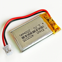
Typical digital electronics battery (single-cell)

Common R/C hobby battery (multi-cell)
The capacity of a battery is measured in milliamps per hour (mAh). If a battery contains 500mAh, that means it can deliver a current of 500mA during one hour. That is a current of 1C - one time the capacity. It means it can also supply a current of 250mAh (0.5C) for two hours. If the current is 50mA (0.1C), the battery can last for 10 hours.
These batteries are pretty much everywhere nowadays. They power your smartphone, tablet, laptop computer, headphones, and many more.
Dangers of LiPo
Fact: LiPo batteries are dangerous. They can heat up and burst into flames if handled improperly.
What exactly do we mean by "heat up"? The images below provide some examples:

While this may be scary (and it should) we still use LiPos everywhere all the time.
If handled properly, LiPo batteries are incredibly useful and can provide consistent power after re-charging for hundreds or even thousands of cycles.
Mostly, this all comes down to three key aspects:
- thermal - Don't expose the battery to extreme cold / hot (keep it between 0 and 50 deg. C)
- mechanical - don't puncture, cut, hit, crush or otherwise torture the battery
- electrical - don't over-draw it (pull too many amps or get it below ~2.7V) and carefully follow the charging curve
The thermal and mechanical parts shouldn't usually be a problem. For the electrical part, there are two things we need to look at:
- discharging - should not pull more than 1C and should not go below 2.7V
- re-charging - should be done according to a precise voltage / current curve

LiPo battery and protection circuit (separated)
The protection circuit
LiPo batteries can be equipped with a protection circuit which ensures it only operates within allowed thresholds. Most batteries used for embedded electronics feature these protection circuits.
In the R/C world
Because protection circuits effectively limit the current that can be pulled from a battery, those are not suited for high-power applications like R/C vehicles. These simply go without any protection and it's basically up to the user to make sure they don't push the battery beyond its limits (though the vehicle's electronics often provide some assistance).
Keep it safe
We only use batteries with protection circuits here at Dooba, and highly recommend you do the same unless you are very experienced with this technology.
Charging
In addition to limiting the discharge, we need to precisely control the voltage and current (amps) in order to correctly and safely charge a battery.
While this precise control could be done by hand or using some arrangement of discrete components, many IC's (integrated circuits) today provide exactly this functionality and are much smaller, cheaper and easier to integrate.

Nomad - LiPo battery management module
The Nomad module
The Nomad is a small LiPo battery management module. It's purpose is to make using LiPo batteries as easy as possible.
To do this, it provides the following:
- charge control (voltage/current curve)
- charge indicator output
- clean dual output (5.0V & 3.3V)
- battery level indicator output

The Nomad module
Basically, you hook a battery to one side of the module and your application to the other side. The module also accepts a 5.0V input to charge the battery - this is usually connected to USB power (for example through the ioNode) to allow charging simply by plugging the USB.
[!] WARNING - make sure the VIN-VUSB jumper on the ioNode is removed when using VIN and VUSB separately! Have a look at ioNode's VIN-VUSB jumper to know more.
The Nomad will provide two stabilized outputs: 5.0V and 3.3V. When the input is present (and the battery is not full), the module will charge the battery at a rate of 100mA.
Attaching the battery
Note: the Nomad module does NOT include a battery, you need to provide one. Any single-cell LiPo with protection circuit (not the kind used for most R/C stuff) of minimum 100mAh will do.
Ebay is a good place to look for LiPo batteries.
We need to attach the battery's positive terminal (RED wire) to the "BAT+" pin of the Nomad, and the battery's negative terminal (BLACK wire) to the "BAT-" pin of the Nomad.
The picture below shows exactly this:

We can either attach the battery wires directly, or use a standard connector (such as JST, JR, or any other). In any case, always watch the polarity! Again, Red wire goes to "BAT+", black wire goes to "BAT-".
Battery wires can be quite fragile. One recommendation if you are having mechanical failures on the battery wires is to add some glue (hot glue or similar) around the solder points to "strengthen" the whole assembly.

Nomad module with battery attached trough a JST connector
Complete power system
Let's use what we saw above to setup an ioNode with a Nomad for a portable project which we can charge via USB.
Wiring
The wiring for this setup is pretty simple. First, we want the Nomad to provide power to the ioNode, so we need to connect the 5.0V output from the Nomad to the VIN of the ioNode.

Next, we want the ioNode's USB to power the Module for charging the battery, so we need to connect the ioNode's VUSB to the Nomad's VIN.
Whenever the ioNode's USB is plugged to a computer or power source, the module will be able to charge the battery if needed.

Then, we want to be able to monitor the battery's state from our application.
For this, we will need to connect the Nomad's CHARGING indicator output to any digital input (GPIO) on the ioNode.
To determine the current battery level we will also need to connect the Nomad's BAT_LEVEL output to any analog input (ARD) on the ioNode.

You might notice in this example that we used pins P0 and P1 for BAT_LEVEL and CHARGING. While BAT_LEVEL is an analog signal (therefore requiring an analog input pin), CHARGING is a digital signal that may be connected to any GPIO.
We used P1 (which can also serve as analog input) to keep the wires short and the example simple, but we could've used any other pin.
Finally, just like for any digital design, we need to have a common ground between the Nomad module and our ioNode - let's make sure all the grounds are connected together.

That's it! Below is the final result showing all connections:

Code
As seen previously, we wired up two signals from the Nomad module to our ioNode:
- BAT_LEVEL
- CHARGING
These allow us to monitor the battery from our code. We can use the 'nomad' library to do just that, so let's start by adding it to our list of dependencies in dfe.conf:
# ...
deps:
  - nomad
Now we can initialize the library. As always, we can do this through the substrate or manually from C code. Using the substrate is recommended as it will keep our code shorter and simpler.
Substrate initialization
We can define our Nomad battery module and its wiring in our substrate file:
# Nomad battery module using pins 0 & 1
uses :nomad, name: 'bat0', bat_level_pin: 0, charging_pin: 1
This will create a nomad structure pointer 'bat0' (struct nomad *bat0;).
Manual initialization (without substrate)
We can achieve the same results as above manually from our C code:
 1 #include <nomad/nomad.h>
 2
 3 // Nomad module
 4 struct nomad bat0_data;
 5 struct nomad *bat0;
 6
 7 void main()
 8 {
 9     // Initialize Nomad module (using pins 0 & 1)
10     nomad_init(bat0, 0, 1);
11
12     // ...
13 }
Reading battery voltage, percentage & charging status
Now that we're all set up, we can actually monitor the battery:
 1 void main()
 2 {
 3     uint16_t v;
 4     uint8_t pct;
 5
 6     // ...
 7
 8     // Get battery voltage (in millivolts)
 9     v = nomad_get_vbat(bat0);
10
11     // Get battery percentage
12     pct = nomad_get_bat_pct(bat0);
13
14     // Check charging status
15     if(nomad_is_battery_charging(bat0))    { /* Battery is charging */ }
16     else                                   { /* Battery is NOT charging */ }
17
18     // ...
19 }