ioNode
Introduction
The ioNode is an embedded development board. It allows programming some logic to control inputs & outputs at an electronic level.
It is easily programmed (or "flashed") from a host computer through USB.
If you want to know how to program this device, please have a look at our tutorial.
Specifications
- Power input: 4.0V - 6.0V
- Microcontroller: Microchip ATMEGA1284P
- CPU Frequency: 10MHz
- RAM: 16Kb
- Flash: 128Kb
- LEDs: 4 (PWR, ACT, USB TX/RX)
-
Digital I/O pins: 29 (30 - 1 used for onboard ACT LED)
- Analog input: 8
- PWM: 7 (8 - 1 used for onboard ACT LED)
- Interfaces:
Pinout
The diagram below shows the pin assignments for the ioNode:

I/O Pins
The ioNode features 30 I/O's labeled P0 - P29.
Pin P12 is special - it is directly wired to an onboard activity LED ("ACT"). All 29 other I/O lines (P0-P11 & P13-P29) are exposed as physical pins on the sides of the board.
Many of these also have alternate functions.
The first 8 can be also used as analog inputs (P0-P7). Some others can function as PWM outputs (P11, P12, P14, P15, P18, P19, P20, P21).
Pins P13 - P15 also form the SPI bus, while pins P22 & P23 make up the I2C bus. Finally, pins P16 & P17 are the RX & TX lines of UART1.
USB
A Micro-B USB port and USB UART (Serial-to-USB) allow for simple communication with any host computer without needing specific drivers.
When plugged in, the ioNode appears to the host as a standard serial port.
The same USB can therefore be used to program the device, as well as for communication between the application running inside the ioNode and a host computer.
Power
The ioNode has a rather flexible power supply model, allowing for many various scenarios.
As input, it requires between 4V and 6V of DC current on the VIN pin.
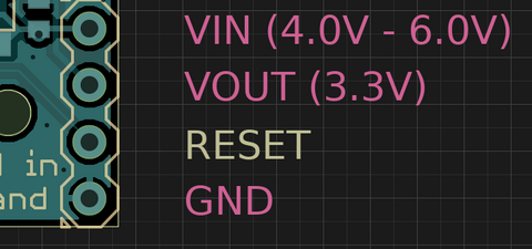
Simply connect the "+" side of a voltage source to the VIN pin shown above. Connect the "-" side of the voltage source to any GND pin. That's it! The ioNode will start running whatever application is stored in its flash memory.
Power Output
The ioNode uses a regulated 3.3V supply internally. This regulated 3.3V is exposed as a VOUT pin (visible on the picture above).
Use it to power whatever component / module you need, but pay attention to the consumption (amps) - the ioNode can provide up to 500mA.
Going over this limit will produce unpredictable results.
Using USB for power
One of the nice features of the USB standard is that the host must provide 5V to devices. On the ioNode, this 5V from USB is exposed as a VUSB pin.

Since 5V is within the 4V ~ 6V range needed to run the ioNode, we can simply connect VUSB and VIN, and the ioNode will run as soon as it is plugged into USB.
To make things even simpler, a solder jumper is present on the ioNode to do just that (connecting VUSB and VIN).
All ioNodes purchased through the Dooba web shop are shipped with this jumper soldered by default.

If we are NOT powering the ioNode directly from the USB (for example when using a LiPo battery), we should remove (de-solder) this jumper.
This makes power management fairly simple for any USB-based project.
Schematic
